Identify the locations that warrant attention in a joint group.
Organize long-term observation around the bolt ring, periodic retesting, link status, and maintenance records
Ultrasonic bolt force monitoring and maintenance
From one inspection to ongoing monitoring.
Keep location, measurement and maintenance in one service history.
Critical bolted joints · Wind turbine blade root example
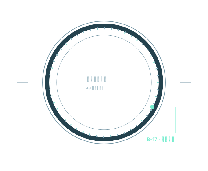
Bolt force at the reference condition 84.5% of baseline
Looking down along the variationThe scale shows bolt force as a percentage of baseline. The joint and monitoring history are illustrative.
Periodic retests provide distinct observations. Online monitoring records continuous changes.
Compare the records at the same location, for the same bolt and under comparable conditions.
Select two records to compare measurement conditions and bolt force.
From echo to time of flight, and from calibration to bolt force. Interpret changes using the measurement location, reference, temperature and events in the measurement chain.
Synthetic waveforms and simplified conversions illustrate the measurement chain. The research data is shown separately below.
The demo uses a linear sensitivity of 0.42 kN/ns and a temperature coefficient of 0.58 ns/°C. The observed time-of-flight change includes contributions from bolt force, temperature, and possible measurement-chain drift. Subtracting the temperature term leaves any measurement-chain drift unresolved. These coefficients are demo inputs independent of the study data below and are unsuitable for field setup.
Zero load measurement reference is used for axial force conversion, service baseline is used for historical comparison. Replacing bolts requires new individual records; if there is a missing baseline, data interruption, or reference to be verified, direct decay conclusions are not output.
Discovery, verification, maintenance, re-verification. Each step returns to the same bolt position, retaining the original basis and leaving subsequent changes.
Verify the current focus in terms of spatial position, history, and measurement conditions.
Clearly check the object and measurement premise, retain new re-measurement results.
Record processing events, compare subsequent valid results, and retain the previous history.
Operable preset maintenance scenarios; tasks and records are only demonstrated within the current browser page
 TD SentinelInspection summary / example
Exported content follows the current measurement point, time, rules, and task status, with a scenario data identifier included.
AI monitoring assistant works by starting with understanding the current joint. Compare records, locate references, organize re-measurement tasks, keeping analysis and action aligned.
Around the currently selected bolt, view measurement, history, and maintenance basis.
Current work focuses on ultrasonic calibration, hysteresis and measurement stability. These studies help convert measurement prerequisites into clear records in the software.
Fitting only explains the relationship of this set of data, does not represent device accuracy or long-term monitoring accuracy
A single measurement must be saved together with the bolt individual, reference state, and calibration relationship. The model's applicability and actual measurement conditions should also be considered as results are seen.
Existing research has also analyzed repeated measurements under fixed conditions, link reconnections, and changes in monitoring objects. Long-term serviceability will continue to rely on field data and independent verification.
Data is organized from historical ultrasonic axial force calibration records, including 50 sets of time of flight differences and external loads, with project and field identities removed.
Place two observations on the same time scale. Retain waveform contours, time of flight readings, and link events, making changes traceable.
Move or Tap the Curve to View Time Position
The change in readings needs to be interpreted together with the connection event and reference state.
Redraw based on historical test screenshots. The curve retains the upper and lower contours of visible trajectories, not the original sampling data; time of flight readings are preserved as in the original image.
The source comprises earlier and later records from one brief sensor-detachment test (11.JPG and 21.JPG, TchUS8 V3.1). The horizontal axis follows the time scale of the original screen. The vertical axis shows normalized amplitudes on a common image scale. The traces were extracted from the screenshots for visual waveform comparison. They cannot recover the original sampled sequence. The time-of-flight difference of 2.04 ns was read from the screen. The reconstructed curves do not establish that value, causation, or device accuracy.
TD Sentinel is in the product development stage. This page shows the product direction; the monitoring interface uses synthetic scenarios, and the points and historical echoes are separately marked with sources.
Organize positions by connection objects, comparisons by measurement conditions, and maintenance events by history. This method should be able to expand with scenarios.
Organize long-term observation around the bolt ring, periodic retesting, link status, and maintenance records
Retain measurement point identity, reference conditions, and inspection batch, trace the state changes of the same connection
Organize data integration and maintenance collaboration for inspectors, equipment management, and technical teams
Load correlation, fatigue damage, and life studies are part of the future product direction. They require real load spectra, materials, connection models, operating conditions, and independent verification to support them.
TD Atlas Provide knowledge, standards, and method basis. If service changes require further verification,TD Nexus Focusing on Overall Load Path and Connection Group ResponseTD Forge Facing thread profile, thread root and engagement area details; analysis still needs to be supplemented with real operating conditions, materials and boundary conditions.
Cross-product data collaboration belongs to the kit planning direction, specific integration is subject to official release notes.
Start with a specific structure, measurement condition, or maintenance issue
Discuss how Sentinel can enter your workflow.